Deuterium pulse width calibration and decoupling: Difference between revisions
| (One intermediate revision by the same user not shown) | |||
| Line 63: | Line 63: | ||
At this step you will need the <tt>H2_pwxcal</tt> dataset. If you don't have this dataset, install it: | At this step you will need the <tt>H2_pwxcal</tt> dataset. If you don't have this dataset, install it: | ||
#Downloading [[ | #Downloading [[File:H2_pwxcal.tar.gz]] into your VNMRJ user home directory | ||
#Ucompress and unpack it | #Ucompress and unpack it | ||
#Go to <tt>~/vnmrsys/psglib/</tt> and compile the pulse sequence with <tt>seqgen H2_pwxcal.c</tt> | #Go to <tt>~/vnmrsys/psglib/</tt> and compile the pulse sequence with <tt>seqgen H2_pwxcal.c</tt> | ||
| Line 78: | Line 78: | ||
#Using the current dataset calibrate the 13C 90-degree pulse with the 360 method, along the lines described for 1H (1H cal).<br>Adjust <tt>tpwr</tt> so that <tt>pw</tt> is equal or greater then the typical <tt>pwC</tt> pulse. | #Using the current dataset calibrate the 13C 90-degree pulse with the 360 method, along the lines described for 1H (1H cal).<br>Adjust <tt>tpwr</tt> so that <tt>pw</tt> is equal or greater then the typical <tt>pwC</tt> pulse. | ||
Please note that 13C T1 relaxation is very slow, and its effect on the accuracy of 13C pulse width calibration is even stronger than for 1H. | Please note that 13C T1 relaxation is very slow, and its effect on the accuracy of 13C pulse width calibration is even stronger than for 1H. | ||
==== 13C Anti-Phase Triplet - Indirect Calibration ==== | ==== 13C Anti-Phase Triplet - Indirect Calibration ==== | ||
[[Image:antiphase_c6d6.png|500px|right]] | [[Image:antiphase_c6d6.png|500px|right]] | ||
Configure the pulse sequence to generate an anti-phase triplet. | Configure the pulse sequence to generate an anti-phase triplet. | ||
| Line 92: | Line 89: | ||
#Set <tt>dof3</tt> to the <tt>tof</tt> value determined from deuterium 1D spectrum | #Set <tt>dof3</tt> to the <tt>tof</tt> value determined from deuterium 1D spectrum | ||
#Run experiment with <tt>go</tt> | #Run experiment with <tt>go</tt> | ||
#Perform FT - you should see the outer lines in anti-phase and the middle line is missing | #Perform FT - you should see the outer lines in anti-phase and the middle line is missing as in the figure on the right. | ||
The pulse sequence now will applies 90x pulse on 13C followed by a delay tau=1/(4*1J_CD) and another 90x pulse on 13C. The outer lines will evolve during tau to antiphase with respect to 2H. Note that the J-coupling evolution here is "twice as fast" as with two spins 1/2! The second 13C pulse is used to suppress the middle line, which does not evolve under J-coupling. | The pulse sequence now will applies 90x pulse on 13C followed by a delay tau=1/(4*1J_CD) and another 90x pulse on 13C. The outer lines will evolve during tau to antiphase with respect to 2H. Note that the J-coupling evolution here is "twice as fast" as with two spins 1/2! The second 13C pulse is used to suppress the middle line, which does not evolve under J-coupling. | ||
[[Image:h2_pulse_calib.png|500px|right]] | |||
Now you can calibrate the deuterium pulse width: | Now you can calibrate the deuterium pulse width: | ||
| Line 102: | Line 101: | ||
#Observe the antiphase triplet decrease linearly and then increase inverted.<br>If you do not see any difference between scans you probably do not have pulsing on deuterium.<br>Type <tt>rftype='dddd' BPsetampmode</tt> to fix it and repeat the experiment. | #Observe the antiphase triplet decrease linearly and then increase inverted.<br>If you do not see any difference between scans you probably do not have pulsing on deuterium.<br>Type <tt>rftype='dddd' BPsetampmode</tt> to fix it and repeat the experiment. | ||
#The zero crossing point corresponds to the desired 90 pulse width. Adjust <tt>dpwr3</tt> so that <tt>pwx3</tt> is ~300 us and repeat the calibration. | #The zero crossing point corresponds to the desired 90 pulse width. Adjust <tt>dpwr3</tt> so that <tt>pwx3</tt> is ~300 us and repeat the calibration. | ||
Fig. 5. Deuterium pulse width calibration. When deuterium pulse with is exactly 90 the outer lines are converted to unobservable MQ coherence. | Fig. 5. Deuterium pulse width calibration. When deuterium pulse with is exactly 90 the outer lines are converted to unobservable MQ coherence. | ||
| Line 111: | Line 106: | ||
Setting '''tof''' to the center line is important here, otherwise the triplet may not be phased properly. | Setting '''tof''' to the center line is important here, otherwise the triplet may not be phased properly. | ||
Adjust '''pw''' to make the center line disappear. | Adjust '''pw''' to make the center line disappear. | ||
==== Deuterium Decoupling Test and Probefile Update ==== | ==== Deuterium Decoupling Test and Probefile Update ==== | ||
Latest revision as of 23:04, 5 January 2010
Pulsing on deuterium is most commonly used as deuterium decoupling in triple-resonance experiments with deuterated samples. Whenever aliphatic 13C magnetization is transverse, it must be decoupled from the attached deuterons. Omitted or improperly calibrated 2H decoupling would cause a sharp sensitivity drop due to scalar relaxation of the second kind [1]. Thus, proper application of 2H decoupling requires tuning the 2H channel and calibrating 2H 90° pulse.
2H 90° Pulse - Automatic Calibration
See 'Chapter 9.0: 2H AutoCalibration' in the BioPack manual.
The automatic calibration method of BioPack uses the same protein sample and calibrates the pulse directly on the HDO signal. It requires a K5022 relay to be present, which allows pulsing deuterium on the 4th channel, while detecting it. At SUNY Buffalo 600 MHz and 750 MHz instruments don't have this relay, therefore requiring manual calibration.
2H 90° Pulse - Manual Calibration
The current protocol is similar to the Calibration via Indirect 2H Detection using 13C Observe section of Chapter 9.0 2H AutoCalibration in theBioPack manual. Though you can still use the ddec_pwxcal dataset as recommended in the BioPack manual, the method presented here is more accurate and easier to use.
Manual calibration of deuterium 90° pulse requires an ASTM standard test sample, which contains 60% benzene-d6 (C6D6) and 40% dioxane. The chemical shifts of benzene are 7.15 ppm (2H) and 128.0 ppm 13C (see http://www.sdsnmr.com/cs_table.html) and the scalar coupling 1JCD is 24 Hz. Note that 2H and 1H shifts are essentially the same and that benzene-d6 contains 13C at natural abundance level.
- Insert the ASTM sample
- Tune the 13C and 2H channels as described on the tuning page.
- Lock the sample on the benzene-d6 signal; z0 will be different from that when locking on D2O!
- Shim the sample as described on the shimming page. You can use 1H gradient shimming on the dioxane resonance.
1D Deuterium Spectrum
Typical 2H 90° pulse width for decoupling is in the order of 200-300 us. With a pulse that long, it is important to know the exact 2H offset of benzene-d6 to ensure on-resonance condition during calibration. You can use a 1D deuterium spectrum of the test sample to find the resonance. This experiment will also test if you can pulse and detect deuterium on the first channel.
The current protocol is based on the "Directly Observing Deuterium" in the Deuterium Decoupling Channel Installation manual with small modifications. To record a 1D deuterium spectrum do the following:
- Turn lock off and connect the cable from J1 PROBE port on the 2H decoupler/lock diplexer to the J5311 PROBE probe port on the broadband preamp with the 2H RF filter in line.
- On 750 MHz instrument with a cryogenic probe you additionally have to:
- Disconnect the 13C cable from the BE188-20-7BB filter on the console side
- Connect this cable through the BE135-35-8BB filter to the XMTR J5313 port on the broadband preamp
- Retrieve parameter set /vnmr/tests/C13sn. This will also set solvent='c6d6'
- Make the following changes: numrfch=4 rftype='dddd' tn='H2' tpwr=43 pw=250 dn=dm='nnn' dn2= dm2='nnn' dn3=dm3='nnn' at=1 d1=1 nt=1 ss=2 in='n'
- Set tof=(7.15-5)*sfrq to move the carrier closer to the benzene-d6 line
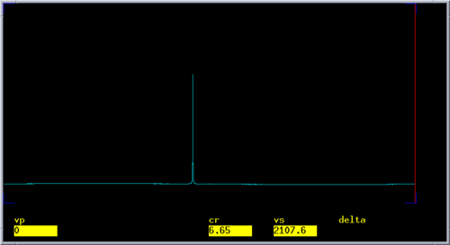
- Acuire the spectrum with go and perform FT with a large fn value. You should see a signle line.
- Phase the spectrum and center the cursor on the line. Use movetof so set the carrier offset on the resonance. Write down the new tof value.
- Re-connect all cables to their original positions and activate lock
Even though you can now calibrate the deuterium 90-degree pulse directly with this experiment, it may not exactly be the one you need for decoupling. In direct observe mode deuterium is on the first channel, while in a triple-resonance experiment it is on the fourth channel, and the RF path goes through different amplifiers.
Indirect Calibration - 1D 13C spectrum
Configure the spectrometer for 13C direct detection:
On 600 MHz (SUNY Buffalo):
- Connect the cable from K5006 port at the back of the box to the J5311 PROBE probe port on the broadband preamp with the 13C RF filter in line.
On 750 MHz (SUNY Buffalo):
- Locate the cable going from the 13C port on the probe to an RF filter, and disconnect it from the RF filter.
- Get a free cable and an identical filter, and connect it to the PROBE J5311 port on the broadband preamp.
- Get a free cable and connect the first RF filter to the XMTR J5313 port on the broadband preamp.
13C In-Phase Triplet
At this step you will need the H2_pwxcal dataset. If you don't have this dataset, install it:
- Downloading File:H2 pwxcal.tar.gz into your VNMRJ user home directory
- Ucompress and unpack it
- Go to ~/vnmrsys/psglib/ and compile the pulse sequence with seqgen H2_pwxcal.c
Before proceeding with deuterium 90 pulse calibration you need to verify that you can pulse and detect C13 as the 1st channel. You will also need do determine the 13C 90-degree pulse width.
- Type H2_pwxcal to load the custom dataset.
- Set anti='n' lkflg='y' dm3='nnn' pwx3=0 rftype='dddd' ampmode='dddp' tof=(128-92)*sfrq sw=10000 at=0.3 d1=5 ss=0 nt=1 fn=64k
- Set pw to the typical pwC value; keep the current tpwr or set tpwr to pwClvl, whichever is smaller.
- Run go to acquire spectrum
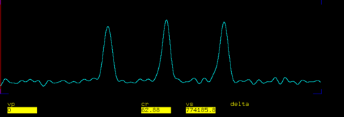
- Disable weighting functions and do FT. You should see an in-phase 1:1:1 triplet split by the 1J_CD coupling.
- Place the cursor on the middle line and type movetof to reset tof.
- Set sw=1000 and acquire the spectrum again.
- Using the current dataset calibrate the 13C 90-degree pulse with the 360 method, along the lines described for 1H (1H cal).
Adjust tpwr so that pw is equal or greater then the typical pwC pulse.
Please note that 13C T1 relaxation is very slow, and its effect on the accuracy of 13C pulse width calibration is even stronger than for 1H.
13C Anti-Phase Triplet - Indirect Calibration
Configure the pulse sequence to generate an anti-phase triplet.
- Set anti='y' pwx3=0
- Set jCD=24 for benzene-d6 - you can measure is from the splitting.
- Set dof3 to the tof value determined from deuterium 1D spectrum
- Run experiment with go
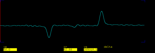
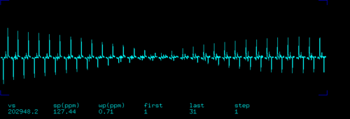
- Perform FT - you should see the outer lines in anti-phase and the middle line is missing as in the figure on the right.
The pulse sequence now will applies 90x pulse on 13C followed by a delay tau=1/(4*1J_CD) and another 90x pulse on 13C. The outer lines will evolve during tau to antiphase with respect to 2H. Note that the J-coupling evolution here is "twice as fast" as with two spins 1/2! The second 13C pulse is used to suppress the middle line, which does not evolve under J-coupling.
Now you can calibrate the deuterium pulse width:
- Set dpwr3=40 ss=4 nt=1
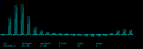
- Array pwx3 from 0 to 1000 in steps of 50
- Observe the antiphase triplet decrease linearly and then increase inverted.
If you do not see any difference between scans you probably do not have pulsing on deuterium.
Type rftype='dddd' BPsetampmode to fix it and repeat the experiment. - The zero crossing point corresponds to the desired 90 pulse width. Adjust dpwr3 so that pwx3 is ~300 us and repeat the calibration.
Fig. 5. Deuterium pulse width calibration. When deuterium pulse with is exactly 90 the outer lines are converted to unobservable MQ coherence.
Setting tof to the center line is important here, otherwise the triplet may not be phased properly.
Adjust pw to make the center line disappear.
Deuterium Decoupling Test and Probefile Update
To test 2H CPD decoupling:
- Set dmf3=1000000/pwx3, where pwx3 is the true 90 degree pulse width.
- Set rftype='dddd' BPsetampmode anti='n' dm3='nnn' dmm3='ccw' pwx3=0 at=0.06 sw=10000 nt=1 ss=0.
- Acquire and transform the spectrum. The result should be the familiar uncoupled in-phase triplet, though at a lower resolution.
- Set dm3='nny' to enable decoupling.
- Acquire and transform the spectrum. The result should be the decoupled single peak.
Here acquisition time is set to 60 ms, because deuterium decoupling should not be used with long duty cycles.
To update the probe file
- Set dof3=(3-5)*dfrq3 to set default carrier at ~3 ppm
- In the Setup -> Globals&Calibration click on the H2 button
Also see the instructions given in man('BioPacklist').
For details on probefile update see Manual Probefile Update page.
Using 2H Decoupling With Deuterated Protein Samples
At this point you have calibrated deuterium 90-degree pulse width and updated the probefile.
For every new sample make sure to tune the 2H channel, including the next protein sample following the calibration with ASTM.
Deuterium decoupling parameters are read automatically when you load a <nop>BioPack dataset with a corresponding macro, provided that numrfch=4 is set. Deuterium decoupling is off by default, however. After you load a dataset you should usually set dn3='H2' dm3='nyn' to turn it on. Refer to the pulse sequence manual for detailed instructions.
Make sure you are using the correct offset dof3 for decoupling. The value used with C6D6 corresponds to 7.15 ppm. The default value in the probefile should correspond to ~3 ppm. If you are running an experiment like HNCA you may want to set it to 4.5 ppm.
To test 2H decoupling for a protein sample you may take a concentrated DCN sample and run the first increment of HNCA with constant-time Ca evolution, switching deuterium decoupling on and off. If decoupling is working properly, you should see a significant sensitivity difference.
References
- ↑ Murali, N., Rao, B.D.N. (1996) Lineshape variations of a spin-1/2 nucleus coupled to a quadrupolar spin subjected to RF irradiation. JMR, Series A, 202(3), 215-221
