Deuterium Lock: Difference between revisions
No edit summary |
No edit summary |
||
| (11 intermediate revisions by 3 users not shown) | |||
| Line 1: | Line 1: | ||
The lock system keeps the spectrometer operating at a constant net magnetic field. It compensates for the drift of the superconducting magnet's field and other instabilities. The current in the <tt>z0</tt> coil is adjusted so that the lock resonance matches a predefined frequency <tt>lockfreq</tt> . Before activating the lock system you have to find the lock resonance. | |||
For detailed information on locking you sample see | |||
*[http://www.varianinc.com/image/vimage/docs/products/nmr/apps/pubs/manuals/0199916000b.pdf VNMR 6.1C Getting Started Manual] | |||
* [http://www.varianinc.com/image/vimage/docs/products/nmr/apps/pubs/manuals/0199916000b.pdf VNMR 6.1C Getting Started Manual] | *[http://www.varianinc.com/image/vimage/docs/products/nmr/apps/pubs/manuals/0199931300b.pdf VNMRJ Liquids NMR Users Guide], section 3.7 | ||
* [http://www.varianinc.com/image/vimage/docs/products/nmr/apps/pubs/manuals/0199931300b.pdf VNMRJ Liquids NMR Users Guide], section 3.7 | *BioPack manual | ||
* BioPack manual | |||
Note that BioPack installation alters the interface described in the original manuals. | Note that BioPack installation alters the interface described in the original manuals. | ||
== | == Finding Lock Signal Manually == | ||
First you must start the lock signal display. The channel selector for probe tuning should be at 0. | First you must start the lock signal display. The channel selector for probe tuning should be at 0. | ||
In VNMR: | In VNMR: | ||
#Click on the '''Acqi''' button or type <tt>acqi</tt> to open the acquisition window. | |||
# | #Click in the '''Lock''' button in the acquisition window | ||
# Click in the '''Lock | |||
In VNMRJ: | |||
#Go to the '''Setup''' tab; click on the '''Lock''' tab to see the adjustable parameters | |||
#Click in the '''Lock Scan''' button in the middle of the screen | |||
[[Image:Vnmrj lock.png|606x172px]] | |||
Make sure the the lock system is not activated: | |||
*In VNMR click on the '''LOCK:off''' button in the acquisition window; <span style="color: green;"> LOCKED </span>should change to <span style="color: red;"> LOCK OFF </span> | |||
*In VNMRJ uncheck the '''Activate Lock''' checkbox | |||
Adjust lock power to | Adjust <tt>z0</tt> to locate the lock resonance. You may increase lock power and gain to see the signal better. When manually adjusting <tt>z0</tt> the following rule holds: the closer you are to the resonance, the fewer sinusoid "beats" you see. When on-resonance you should see a straight line. The figures below show examples from a typical locking process. | ||
[[Image:Lock a.jpg|205x273px|lock off-resonance]][[Image:Lock b.jpg|205x273px|lock closer to resonance]][[Image:Lock c.jpg|205x273px|lock on resonance]]'''<br>''' | |||
<br> | |||
Activate the lock system: | |||
*In VNMR click on the '''LOCK:on''' button in the acquisition window; <span style="color: red;"> LOCK OFF </span> should change to <span style="color: green;"> LOCKED </span> | |||
*In VNMRJ check the '''Activate Lock''' checkbox | |||
Adjust lock phase to maximize the lock signal. You may actually need to re-optimize lock phase after shimming. | |||
In | Adjust lock power to maximize the signal while avoiding saturation. In the unsaturated state decreasing lock power by 6 dB should make the lock level drop by one half. Under saturating conditions the lock resonance is distorted and this may pose a problem for shimming on the lock. | ||
Adjust lock gain to maximize the lock signal. Since it controls the amplification of the lock signal, increasing lock gain will increase both lock level and its noise. | |||
Normally you want to have the highest non-saturating <tt>lockpower</tt> and the lowest <tt>lockgain</tt>, which yield an acceptable lock level. Lock level should be above ~20 for the sample to be locked. The lock level will usually increase after you shim the sample. It should be ~50 or higher before you run a real experiment, because if the level drops below 20 during acquisition (due to gradients, for example) lock may be lost. | |||
Also, tuning the lock channel may improve sensitivity. Lock channel tuning is normally available on cryprobes. | |||
The | The field produced by the <tt>z0</tt> coil has some slight z-dependence (mainly linear), which is usually compensated during shimming. On machines with very large field drift this may require use of hardware autoshim during long-term experiments. | ||
== Finding Lock Signal Automatically == | |||
In VNMRJ: | |||
#Go to the '''Setup''' -> '''Lock''' tab | |||
#Click on the '''Find Lock''' button | |||
This procedure usually takes longer, but may be useful if cannot find the lock resonance manually. | |||
=== '' | Note that you will still need to manually adjust lock power to avoid lock saturation. | ||
== Temperature Dependence == | |||
The position of the water line in 1H or 2H spectra has a strong dependence on temperature. Since lock tries to match the deuterium resonance of water to a predefined frequency, <tt>z0</tt> will be different at different temperatures. | |||
It also means the total <tt>B0</tt> field will be different even for the same spectrometer and sample locked at different temperatures. Thus, the DSS spectrum should be acquired at the same temperature as the protein sample being referenced. Alternatively, the DSS line position can be tabulated at various temperatures and it temperature dependence determined by a linear regression - this referncing method is employed by Agnus. This referencing method is also unaffected by <tt>lockfreq</tt> reset (see below). | |||
== Solvent dependence == | |||
Deuterons in different solvents resonante at different ppm positions. The lock system, however, would adjust them to the same predefined frequency. Thus, a locked sample in D2O will experience a different B0 field than a locked sample in C6D6. | |||
To make sure that the carrier offsets (<tt>tof</tt>, <tt>dof</tt>, <tt>dof2</tt>) remain unchanged, the lock solvent has to be specfied by setting the <tt>solvent</tt> variable. For example, for protein samples <tt>solvent='d2o'</tt>. For proper names of other lock solvents see the <tt>/vnmr/solventlist</tt> file in your VNMR or VNMRJ installation | |||
== Resetting Lock Frequency == | |||
Locking requires setting <tt>z0</tt> so that the deuterium resonance of the solvent (D2O in protein NMR) matches the lock frequency <tt>lockfreq</tt> of the spectrometer. One day you may find that the lock resonance is beyond the operating range of <tt>z0</tt>. In this case it is necessary to reset <tt>lockfreq</tt> to a lower value. This parameter has to be changed on 500MHz, 600MHz and 750MHz instruments in Buffalo about once or twice a year depending on the field drift. | Locking requires setting <tt>z0</tt> so that the deuterium resonance of the solvent (D2O in protein NMR) matches the lock frequency <tt>lockfreq</tt> of the spectrometer. One day you may find that the lock resonance is beyond the operating range of <tt>z0</tt>. In this case it is necessary to reset <tt>lockfreq</tt> to a lower value. This parameter has to be changed on 500MHz, 600MHz and 750MHz instruments in Buffalo about once or twice a year depending on the field drift. | ||
Run <tt>config</tt> to open a spectrometer configuration window and key in the new frequency there, then type <tt>su</tt> to enable the new setting. Record this event in | Run <tt>config</tt> to open a spectrometer configuration window and key in the new frequency there, then type <tt>su</tt> to enable the new setting. Record this event in the logbook and inform other users of the instrument. You must be running VNMR or VNMRJ as <tt>vnmr1</tt> users to do that. Regular users do not have permissions to modify configuration. | ||
There is always an issue of how big the change in <tt>lockfreq</tt> should be. Obviously, it should not be so small that you will have to do it again next week, and should not be too large that your <tt>z0</tt> is out of range in on the opposite side. | There is always an issue of how big the change in <tt>lockfreq</tt> should be. Obviously, it should not be so small that you will have to do it again next week, and should not be too large that your <tt>z0</tt> is out of range in on the opposite side. | ||
For example, for both 600 MHz and 750 MHz spectrometers in Prof. Szyperski's lab one unit of <tt>z0</tt> is equivalent to approximately 0.05 Hz. Since <tt>z0</tt> has a range of -32767 to 32767, <tt>lockfreq</tt> can be safely changed by about 2700 Hz. Field drift rate of 600 MHz spectrometer was found to be ~315 <tt>z0</tt> units/day or ~16 Hz/day. The drift rate of 750 MHz is ~100 <tt>z0</tt> units/day or ~5 Hz/day. Therefore, <tt>lockfreq</tt> needs to be reset about twice a year on 600 MHz and once every year and a half on 750 MHz. | |||
Field drift rate of 600 MHz spectrometer was found to be ~315 <tt>z0</tt> units/day or ~16 Hz/day. The drift rate of 750 MHz is ~100 <tt>z0</tt> units/day or ~5 Hz/day. Therefore, <tt>lockfreq</tt> needs to be reset about twice a year on 600 MHz and once every year and a half on 750 MHz. | |||
'''DO NOT''' type something like <tt>lockfreq = 99.999</tt> at the prompt. This would only be valid until you restart VNMR or VNMRJ and is grossly confusing. | '''DO NOT''' type something like <tt>lockfreq = 99.999</tt> at the prompt. This would only be valid until you restart VNMR or VNMRJ and is grossly confusing. | ||
| Line 87: | Line 90: | ||
'''IMPORTANT!''' Changing <tt>lockfreq</tt> significantly affects referencing with DSS, since you change the B0 field of the spectrometer. '''Always''' record a 1D DSS spectrum with a new <tt>lockfreq</tt>. | '''IMPORTANT!''' Changing <tt>lockfreq</tt> significantly affects referencing with DSS, since you change the B0 field of the spectrometer. '''Always''' record a 1D DSS spectrum with a new <tt>lockfreq</tt>. | ||
<br> | <br> | ||
== Working with Bruker Instruments == | |||
The following description pertains to systems with Bruker TopSpin v. 2.0 and higher. | |||
After inserting the sample, the user opens the lock display using the command: | |||
<pre>lockdisp | |||
</pre> | |||
This open the lock display (see below). If unlocked, one observes the ringing signal (left); if locked, then the lock signal is a flat trace (right). | |||
[[Image:Lock unlocked.jpg|400px]][[Image:Lock locked.jpg|400px]] | |||
With the system unlocked: | |||
*Manually adjust the "Field" and "Phase" settings on the BSMS panel, to make the unlocked signal symmetric and centered within the display. | |||
*Then press the "lock" button on the BSMS panel to lock on deuterium. | |||
With the system locked: | |||
*Manually optimize the shims (BSMS panel) by optimizing the height of the lock signal prior to automated shimming routines. | |||
<br> | |||
<br> | |||
== == | |||
<br> -- Main.AlexEletski - 24 Jan 2007 | <br> -- Main.AlexEletski - 24 Jan 2007 | ||
Latest revision as of 16:30, 9 December 2009
The lock system keeps the spectrometer operating at a constant net magnetic field. It compensates for the drift of the superconducting magnet's field and other instabilities. The current in the z0 coil is adjusted so that the lock resonance matches a predefined frequency lockfreq . Before activating the lock system you have to find the lock resonance.
For detailed information on locking you sample see
- VNMR 6.1C Getting Started Manual
- VNMRJ Liquids NMR Users Guide, section 3.7
- BioPack manual
Note that BioPack installation alters the interface described in the original manuals.
Finding Lock Signal Manually
First you must start the lock signal display. The channel selector for probe tuning should be at 0.
In VNMR:
- Click on the Acqi button or type acqi to open the acquisition window.
- Click in the Lock button in the acquisition window
In VNMRJ:
- Go to the Setup tab; click on the Lock tab to see the adjustable parameters
- Click in the Lock Scan button in the middle of the screen
Make sure the the lock system is not activated:
- In VNMR click on the LOCK:off button in the acquisition window; LOCKED should change to LOCK OFF
- In VNMRJ uncheck the Activate Lock checkbox
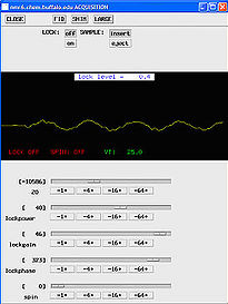
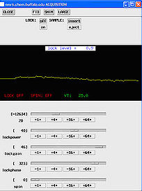
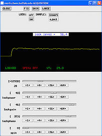
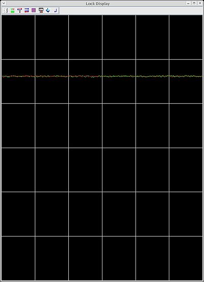
Adjust z0 to locate the lock resonance. You may increase lock power and gain to see the signal better. When manually adjusting z0 the following rule holds: the closer you are to the resonance, the fewer sinusoid "beats" you see. When on-resonance you should see a straight line. The figures below show examples from a typical locking process.
Activate the lock system:
- In VNMR click on the LOCK:on button in the acquisition window; LOCK OFF should change to LOCKED
- In VNMRJ check the Activate Lock checkbox
Adjust lock phase to maximize the lock signal. You may actually need to re-optimize lock phase after shimming.
Adjust lock power to maximize the signal while avoiding saturation. In the unsaturated state decreasing lock power by 6 dB should make the lock level drop by one half. Under saturating conditions the lock resonance is distorted and this may pose a problem for shimming on the lock.
Adjust lock gain to maximize the lock signal. Since it controls the amplification of the lock signal, increasing lock gain will increase both lock level and its noise.
Normally you want to have the highest non-saturating lockpower and the lowest lockgain, which yield an acceptable lock level. Lock level should be above ~20 for the sample to be locked. The lock level will usually increase after you shim the sample. It should be ~50 or higher before you run a real experiment, because if the level drops below 20 during acquisition (due to gradients, for example) lock may be lost.
Also, tuning the lock channel may improve sensitivity. Lock channel tuning is normally available on cryprobes.
The field produced by the z0 coil has some slight z-dependence (mainly linear), which is usually compensated during shimming. On machines with very large field drift this may require use of hardware autoshim during long-term experiments.
Finding Lock Signal Automatically
In VNMRJ:
- Go to the Setup -> Lock tab
- Click on the Find Lock button
This procedure usually takes longer, but may be useful if cannot find the lock resonance manually.
Note that you will still need to manually adjust lock power to avoid lock saturation.
Temperature Dependence
The position of the water line in 1H or 2H spectra has a strong dependence on temperature. Since lock tries to match the deuterium resonance of water to a predefined frequency, z0 will be different at different temperatures.
It also means the total B0 field will be different even for the same spectrometer and sample locked at different temperatures. Thus, the DSS spectrum should be acquired at the same temperature as the protein sample being referenced. Alternatively, the DSS line position can be tabulated at various temperatures and it temperature dependence determined by a linear regression - this referncing method is employed by Agnus. This referencing method is also unaffected by lockfreq reset (see below).
Solvent dependence
Deuterons in different solvents resonante at different ppm positions. The lock system, however, would adjust them to the same predefined frequency. Thus, a locked sample in D2O will experience a different B0 field than a locked sample in C6D6.
To make sure that the carrier offsets (tof, dof, dof2) remain unchanged, the lock solvent has to be specfied by setting the solvent variable. For example, for protein samples solvent='d2o'. For proper names of other lock solvents see the /vnmr/solventlist file in your VNMR or VNMRJ installation
Resetting Lock Frequency
Locking requires setting z0 so that the deuterium resonance of the solvent (D2O in protein NMR) matches the lock frequency lockfreq of the spectrometer. One day you may find that the lock resonance is beyond the operating range of z0. In this case it is necessary to reset lockfreq to a lower value. This parameter has to be changed on 500MHz, 600MHz and 750MHz instruments in Buffalo about once or twice a year depending on the field drift.
Run config to open a spectrometer configuration window and key in the new frequency there, then type su to enable the new setting. Record this event in the logbook and inform other users of the instrument. You must be running VNMR or VNMRJ as vnmr1 users to do that. Regular users do not have permissions to modify configuration.
There is always an issue of how big the change in lockfreq should be. Obviously, it should not be so small that you will have to do it again next week, and should not be too large that your z0 is out of range in on the opposite side.
For example, for both 600 MHz and 750 MHz spectrometers in Prof. Szyperski's lab one unit of z0 is equivalent to approximately 0.05 Hz. Since z0 has a range of -32767 to 32767, lockfreq can be safely changed by about 2700 Hz. Field drift rate of 600 MHz spectrometer was found to be ~315 z0 units/day or ~16 Hz/day. The drift rate of 750 MHz is ~100 z0 units/day or ~5 Hz/day. Therefore, lockfreq needs to be reset about twice a year on 600 MHz and once every year and a half on 750 MHz.
DO NOT type something like lockfreq = 99.999 at the prompt. This would only be valid until you restart VNMR or VNMRJ and is grossly confusing.
IMPORTANT! Changing lockfreq significantly affects referencing with DSS, since you change the B0 field of the spectrometer. Always record a 1D DSS spectrum with a new lockfreq.
Working with Bruker Instruments
The following description pertains to systems with Bruker TopSpin v. 2.0 and higher.
After inserting the sample, the user opens the lock display using the command:
lockdisp
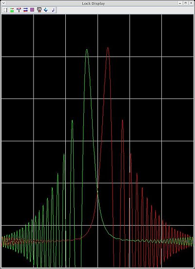
This open the lock display (see below). If unlocked, one observes the ringing signal (left); if locked, then the lock signal is a flat trace (right).
With the system unlocked:
- Manually adjust the "Field" and "Phase" settings on the BSMS panel, to make the unlocked signal symmetric and centered within the display.
- Then press the "lock" button on the BSMS panel to lock on deuterium.
With the system locked:
- Manually optimize the shims (BSMS panel) by optimizing the height of the lock signal prior to automated shimming routines.
-- Main.AlexEletski - 24 Jan 2007

